In Ogre Procedural, shapes, paths and tracks all are made of line connected points.
The difference between them is :
- Tracks are 1D
- Shapes are 2D
- Paths are 3D
Both shapes, tracks and paths can be closed or not : if closed, there will be an automatic junction between the last point and the first point.
Shapes have an outside and an inside : you can define whether the left or the right side is the outside. It also makes sense with non-closed shape (for example, when extruded, the outside corresponds to where the face normal heads). There’s also a function to guess where is the outside and where is the inside.
Splines are a few helper classes used to generate shapes or paths, by interpolating between a bunch of control points.
Tip
You can also generate a track by first generating a shape, then calling the method convertToTrack(). Shape’s X are used as keys and Y as values.
Cubic Hermite Spline. This is often referred as Bezier Spline. With Cubic Hermite Spline, you can choose the points and the tangents of the curves that goes through control points.

Catmull-Rom Spline. It’s a particular case of Cubic Hermite Spline, in which tangents are automatically calculated.
Kochanek Bartels Spline. Kochanek-Bartels spline is defined by control points and 3 parameters : tension, bias and continuity.
Here’s a description of what they do :
| Parameter | +1 | -1 |
|---|---|---|
Tension | Tight | Round |
Bias | Post Shoot | Pre shoot |
Continuity | Inverted corners | Box corners |

Rounded Corner Spline. This one consists in straight lines joining the control points, with corners replaced by circle arcs.

Tracks are used to represent a variable that varies along a path or a shape.
For that reason, the keys of the track are defined relatively to the points in the main curve.
There are 3 different addressing modes :
- AM_ABSOLUTE_LINEIC : the key represents a distance from the beginning of the curve.
- AM_RELATIVE_LINEIC : the key represents a relative distance inside the [0;1] segment, 0 being the beginning and 1 the end of the curve.
- AM_POINT : the key represents the index of a point in the main curve.
You can combine shapes together in order to produce new shapes, using boolean operations. Technically, the output is a multishape, because it doesn’t always resolve to a single line.
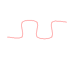
As an exemple, let’s say we have these 2 shapes :

Supported boolean operations are :
- Union : the result contains everything inside A plus evertyhing inside B
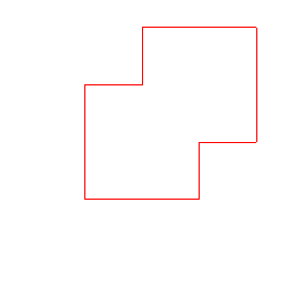
- Intersection : the result contains everything that is inside A and B

- Difference : the result contains everything that is in A but not in B


A constrained triangulation can be performed on a shape or a multishape. It means that points from the shape(s) are joined together to form triangles.
The algorithm used is Bowyer-Watson, which is an implementation of a Delaunay triangulation (Delaunay simply means that triangulation is best quality, ie has as few thin triangles as possible)
